
Page 350 - A Practical Guide from Design Planning to Manufacturing
P. 350
320 Chapter Ten
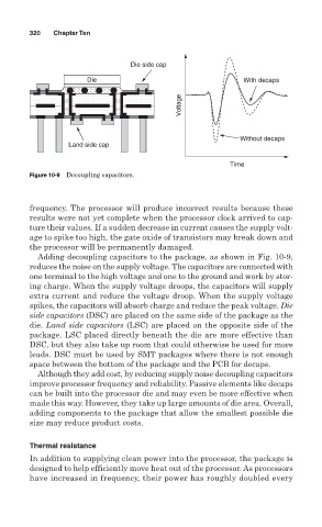
Die side cap
Die With decaps
Voltage
Without decaps
Land side cap
Time
Figure 10-9 Decoupling capacitors.
frequency. The processor will produce incorrect results because these
results were not yet complete when the processor clock arrived to cap-
ture their values. If a sudden decrease in current causes the supply volt-
age to spike too high, the gate oxide of transistors may break down and
the processor will be permanently damaged.
Adding decoupling capacitors to the package, as shown in Fig. 10-9,
reduces the noise on the supply voltage. The capacitors are connected with
one terminal to the high voltage and one to the ground and work by stor-
ing charge. When the supply voltage droops, the capacitors will supply
extra current and reduce the voltage droop. When the supply voltage
spikes, the capacitors will absorb charge and reduce the peak voltage. Die
side capacitors (DSC) are placed on the same side of the package as the
die. Land side capacitors (LSC) are placed on the opposite side of the
package. LSC placed directly beneath the die are more effective than
DSC, but they also take up room that could otherwise be used for more
leads. DSC must be used by SMT packages where there is not enough
space between the bottom of the package and the PCB for decaps.
Although they add cost, by reducing supply noise decoupling capacitors
improve processor frequency and reliability. Passive elements like decaps
can be built into the processor die and may even be more effective when
made this way. However, they take up large amounts of die area. Overall,
adding components to the package that allow the smallest possible die
size may reduce product costs.
Thermal resistance
In addition to supplying clean power into the processor, the package is
designed to help efficiently move heat out of the processor. As processors
have increased in frequency, their power has roughly doubled every