
Page 351 - A Practical Guide from Design Planning to Manufacturing
P. 351
Microprocessor Packaging 321
3
3 years. As transistors have scaled to smaller dimensions, that power is
concentrated in a smaller area. High-performance processors may produce
2
as much as 100 W/cm . Without proper cooling, many processors could
quickly reach temperatures that would cause permanent damage.
Heat is never destroyed; it can only be moved. A refrigerator does not
create cold, it merely moves heat from its interior to the exterior. Leave
the refrigerator door open and in the end the room will get warmer
from the heat of the refrigerator’s motor. The ability of the package and
system to cool the processor is therefore determined by how easily heat
can move. This is typically measured as thermal resistance and has an
important impact on the performance of the processor.
As the power of the processor increases, its temperature will increase.
The difference between the processor temperature and the ambient tem-
perature of its surroundings will increase linearly as more power is applied.
This rate of temperature increase (usually written in degrees Celsius per
watt) is the thermal resistance of the processor. Relatively low-power
processors sometimes rely on heat being transmitted solely through the
leads of the package into the PCB. Higher-power processors must provide
a mechanism for efficiently dissipating heat into the surrounding air.
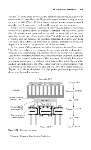
Figure 10-10 shows the parts of a high-power processor package that
determine thermal resistance.
Ambient = 35°C
T ambient = 40°C
Heat sink
Ψ heat sink = 0.5°C/W
Thermal interface
material (TIM) T = 60°C
IHS = 60°C IHS
Die = 100°C
Integrated heat
spreader (IHS) Ψ package = 1.0°C/W
Thermal interface
material (TIM) T die = 100°C
Ψ = 1.5°C/W
Power = 40 W total
Figure 10-10 Thermal resistance.
3
Mahajan, “Emerging Directions for Packaging.”