
Page 141 - Microsensors, MEMS and Smart Devices - Gardner Varadhan and Awadelkarim
P. 141
ISOTROPIC AND ORIENTATION-DEPENDENT WET ETCHING
80 300
60 -
200
40
20 -
0
0 200 400 600 800
Insertion pressure (kPa)
(a)
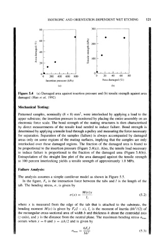
Figure 5.4 (a) Damaged area against insertion pressure and (b) tensile strength against area
damaged (Han et al. 1992)
Mechanical Testing:
2
Patterned samples, nominally (8 x 8) mm , were interlocked by applying a load to the
upper substrate; the insertion pressure is monitored by placing the entire assembly on an
electronic force scale. The bond strength of the mating structures is then characterised
by direct measurements of the tensile load needed to induce failure. Bond strength is
determined by applying a tensile load through a pulley and measuring the force necessary
for separation. Separation of the samples (failure) is always accompanied by damaged
areas only on some regions of the mating surfaces, implying that the samples are only
interlocked over these damaged regions. The fraction of the damaged area is found to
be proportional to the insertion pressure (Figure 5.4(a)). Also, the tensile load necessary
to induce failure is proportional to the fraction of the damaged area (Figure 5.4(b)).
Extrapolation of the straight line plot of the area damaged against the tensile strength
to 100 percent interlocking yields a tensile strength of approximately 1.0 MPa.
Failure Analysis:
The analysis assumes a simple cantilever model as shown in Figure 5.5.
In the figure, F n is the interaction force between the tabs and / is the length of the
tab. The bending stress, a, is given by
M(x)y
a(x) = (5.2)
where x is measured from the edge of the tab that is attached to the substrate, the
3
bending moment M(x) is given by F n(l - x) I z is the moment of inertia (bh /12) of
the rectangular cross-sectional area of width b and thickness h about the centroidal axis
(z-axis), and y is the distance from the neutral plane. The maximum bending stress a max
occurs when x = 0 and y = ±h/2 and is given by
6/y
(5.3)
2
bh