
Page 142 - Microsensors, MEMS and Smart Devices - Gardner Varadhan and Awadelkarim
P. 142
122 SILICON MICROMACHINING: BULK
t t t t t t t t
I I I I I I I I
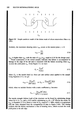
Figure 5.5 Simple cantilever model of the failure mode of silicon microvelcro (Han et al.
1992)
Similarly, the maximum shearing stress r max occurs at the neutral plane >' = 0:
3F n
(5.4)
a max is higher than T max with the ratio of T max/a max equal to h/4l for the design used.
Visual examination of the tested samples indicates that failure is accompanied by
damage to the edge of the tab and is consistent with the failure occurring when a max
exceeds the yield point a yp. From Figure 5.5, we have
_ ext -
r
n — . . \-J-J)
4 sm a
where F ext is the tensile load (i.e. force per unit surface area) applied to the sample.
Using Equation (5.3), we get
" max — • , , i 2 . "• * exi —
2bh sma
which, when we include friction with a static coefficient /z, becomes
2
2a mMbh sin a
ext 2
~ 3d l(\ + Mcota)
The tensile strength (failure load) of the structure can be found by substituting design
5
values for b, h, l, a, and /z (0.5) and by substituting a yp (6 x 10 kPa for the oxide) for
a max in Equation (5.7) to obtain a value of F ext equal to 1.1 MPa, which is in agreement
with the value obtained from the extrapolation of data in Figure 5.4(b). This finding
confirms that the failure mechanism is that of bending stress, which exceeds the oxide
yield point at the tab edge.