
Page 147 - Microsensors, MEMS and Smart Devices - Gardner Varadhan and Awadelkarim
P. 147
ETCH-STOP TECHNIQUES 127
Figure 5.9 Electrochemical cell with 5 percent HF solution to etch silicon. The voltage V a applied
to the silicon is relative to a platinum reference electrode
.0Q.crn(p)
£ 0.3 -
0.01 Q .cm (n)
0.2 -
§ 0.1 h
U 0.3Q«cm(/i)
5 10 15
Voltage V a (v)
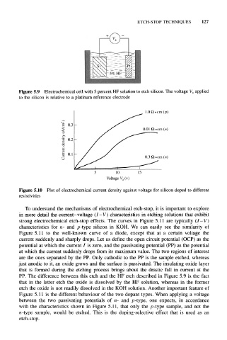
Figure 5.10 Plot of electrochemical current density against voltage for silicon doped to different
resistivities
To understand the mechanisms of electrochemical etch-stop, it is important to explore
in more detail the current-voltage (/- V) characteristics in etching solutions that exhibit
strong electrochemical etch-stop effects. The curves in Figure 5.11 are typically (I-V)
characteristics for n- and p-type silicon in KOH. We can easily see the similarity of
Figure 5.11 to the well-known curve of a diode, except that at a certain voltage the
current suddenly and sharply drops. Let us define the open circuit potential (OCP) as the
potential at which the current / is zero, and the passivating potential (PP) as the potential
at which the current suddenly drops from its maximum value. The two regions of interest
are the ones separated by the PP. Only cathodic to the PP is the sample etched, whereas
just anodic to it, an oxide grows and the surface is passivated. The insulating oxide layer
that is formed during the etching process brings about the drastic fall in current at the
PP. The difference between this etch and the HF etch described in Figure 5.9 is the fact
that in the latter etch the oxide is dissolved by the HF solution, whereas in the former
etch the oxide is not readily dissolved in the KOH solution. Another important feature of
Figure 5.11 is the different behaviour of the two dopant types. When applying a voltage
between the two passivating potentials of n- and p-type, one expects, in accordance
with the characteristics shown in Figure 5.11, that only the p-type sample, and not the
n-type sample, would be etched. This is the doping-selective effect that is used as an
etch-stop.