
Page 143 - Microsensors, MEMS and Smart Devices - Gardner Varadhan and Awadelkarim
P. 143
ISOTROPIC AND ORIENTATION-DEPENDENT WET ETCHING 123
Worked Example E5.2: Undoped Silicon Cantilever Beams
Objective:
To fabricate a cantilever beam oriented in the (100) direction on (100) silicon wafers
(Choit and Smits 1993).
Process Flow:
1. A layer of SiO 2 that is 0.5 um thick is grown on a (100) n-type silicon wafer.
The wafer is spin-coated with a layer of positive photoresist. The masks needed to
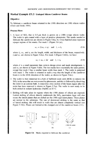
fabricate the cantilevers are shown in Figure 5.6(a, b). Cross-hatched areas represent
opaque regions of the masks. For mask 1 (Figure 5.6 (a)),
w 1 = 2(w b + and (5.8)
where l b, w b, and t b are the length, width, and thickness of the beam, respectively.
and w 1 are shown in Figure 5.6(a). For mask 2 (Figure 5.6(b)), we have
l 1
= w b + and l 2 = (5.9)
where d is a small parameter that corrects design errors and mask misalignment, l 2
and w 2 are shown in Figure 5.6(b). The two masks have essentially the same pattern,
except that mask 2 has a smaller beam width than mask 1. The wafer is patterned
with mask 1. The wafer is oriented in such a way that the length of the cantilever
beam is in the (010) direction of the wafer, as shown in Figure 5.6(c).
2. The wafer is then immersed in a bath of buffered oxide etch (BOE) to remove the
SiO 2 in the areas that are not covered by photoresist, and this is followed by dissolving
the resist in an acetone bath. A transverse cross section of the beam region after the
resist has been removed is shown in Figure 5.7(a). The wafer is now ready to be
bulk-etched in sodium hydroxide (NaOH) at 55 °C.
3. Etching will take place in regions where the (100) planes of silicon are exposed.
Lateral etching of silicon directly underneath the SiO 2 passivation layer will also
occur; the lateral planes that are etched are the (100) equivalent planes. These planes
are normal to the substrates. The rate of downward etching is the same as that
of lateral etching; this will result in walls that are almost completely vertical (see
Figure 5.7(b)). Planes are formed at the clamped end of the cantilever beam (111).
IT
Mask 1
Mask 2
JL
--H h---
W-)
(100) Si wafer
(a) (b) (c)
Figure 5.6 Masks required to fabricate the cantilever