
Page 145 - MODELING OF ASPHALT CONCRETE
P. 145
Complex Modulus fr om the Indir ect Tension Test 123
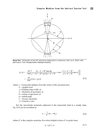
FIGURE 5-1 Schematic of the IDT specimen subjected to a strip load. (Kim et al. 2004, with
permission from Transportation Research Board.)
2
2 P ⎡ ( −1 x / R )sin 2 α ⎧ 1 − x / R 2 ⎫⎤
2
2
σ x () =− ⎢ + tan − 1 ⎨ tanα ⎬⎥
2
y πad 1 + 2 x / R cos 2 α + x / R 4 ⎩ 1 + x / R 2 ⎭⎦
2
2
4
R
⎣
2 P
fx) +
=− [( g x)] (5-5)
(
π πad
where x = horizontal distance from the center of the specimen face
P = applied load
a = loading strip width, m
d = thickness of specimen, m
R = radius of specimen, m
a = radial angle
E = Young’s modulus
n = Poisson’s ratio
For the viscoelastic materials subjected to the sinusoidal load in a steady state,
Eq. (5-3) can be rewritten as
1
ε = ( σ − νσ )
x E ∗ x y (5-6)
∗
∗
where E is the complex modulus. It is often helpful to have E in polar form,
∗
E = E ⋅ e iφ (5-7)
∗