
Page 121 - Modern Control Systems
P. 121
Section 2.8 Design Examples 95
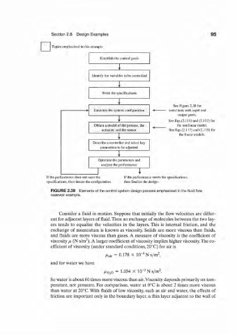
Topics emphasized in this example
Establish the control goals
Identify the variables to be controlled
Write the specifications
v See Figure 2.38 for
Establish the system configuration 4 water tank with input and
output ports.
V SeeEqs.(2.111)and(2.112)for
Obtain a model of the process, the the nonlinear model.
actuator, and the sensor SeeEqs.(2.117)and(2.119)for
the linear models.
v
Describe a controller and select key
parameters to be adjusted
Optimize the parameters and
analyze the performance
:x^ i
If the performance does not meet the If the performance meets the specifications,
specifications, then iterate the configuration. then finalize the design.
FIGURE 2.39 Elements of the control system design process emphasized in the fluid flow
reservoir example.
Consider a fluid in motion. Suppose that initially the flow velocities are differ-
ent for adjacent layers of fluid. Then an exchange of molecules between the two lay-
ers tends to equalize the velocities in the layers. This is internal friction, and the
exchange of momentum is known as viscosity. Solids are more viscous than fluids,
and fluids are more viscous than gases. A measure of viscosity is the coefficient of
2
viscosity /x (N s/m ). A larger coefficient of viscosity implies higher viscosity. The co-
efficient of viscosity (under standard conditions, 20°C) for air is
2
-4
^t air = 0.178 x 10 N s/m ,
and for water we have
2
/JL H2O = 1.054 X 10 -3 N s/m .
So water is about 60 times more viscous than air. Viscosity depends primarily on tem-
perature, not pressure. For comparison, water at 0°C is about 2 times more viscous
than water at 20°C. With fluids of low viscosity, such as air and water, the effects of
friction are important only in the boundary layer, a thin layer adjacent to the wall of