
Page 118 - Modern Control Systems
P. 118
92 Chapter 2 Mathematical Models of Systems
15
____ 1
10
>
j V "'P
1
1 7
i
0.5 1.5 2.5
A^X
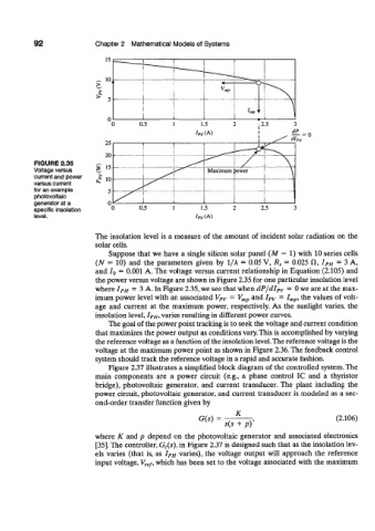
FIGURE 2.35 / \
Voltage versus ^>^*^ Maximum rawer 1 \
current and power
versus current
for an example ,S\ i
photovoltaic i
generator at a ^ 1
specific insolation 0.5 1.5 2.5
level. /PV(A)
The insolation level is a measure of the amount of incident solar radiation on the
solar cells.
Suppose that we have a single silicon solar panel (M = 1) with 10 series cells
(N = 10) and the parameters given by 1/A = 0.05 V, R s = 0.025 ft, I PH = 3 A,
and IQ = 0.001 A. The voltage versus current relationship in Equation (2.105) and
the power versus voltage are shown in Figure 2.35 for one particular insolation level
= = 0 we are at the max-
where I PH 3 A. In Figure 2.35, we see that when dP/dI PV
= = I mpi the values of volt-
imum power level with an associated V PV V mp and I PV
age and current at the maximum power, respectively. As the sunlight varies, the
insolation level, I PH, varies resulting in different power curves.
The goal of the power point tracking is to seek the voltage and current condition
that maximizes the power output as conditions vary. This is accomplished by varying
the reference voltage as a function of the insolation level. The reference voltage is the
voltage at the maximum power point as shown in Figure 2.36. The feedback control
system should track the reference voltage in a rapid and accurate fashion.
Figure 2.37 illustrates a simplified block diagram of the controlled system. The
main components are a power circuit (e.g., a phase control IC and a thyristor
bridge), photovoltaic generator, and current transducer. The plant including the
power circuit, photovoltaic generator, and current transducer is modeled as a sec-
ond-order transfer function given by
G(s) = . K , (2.106)
s(s + p)
where K and p depend on the photovoltaic generator and associated electronics
[35]. The controller, G c(s), in Figure 2.37 is designed such that as the insolation lev-
els varies (that is, as I PH varies), the voltage output will approach the reference
input voltage, V ref, which has been set to the voltage associated with the maximum