
Page 117 - Modern Control Systems
P. 117
Section 2.8 Design Examples 91
of abundant sunlight is a valuable contribution to green engineering (discussed in
Chapter 1). In the second example, we present a detailed look at modeling of the fluid
level in a reservoir. The modeling is presented in a very detailed mariner to emphasize the
effort required to obtain a linear model in the form of a transfer function. The design
process depicted in Figure 1.17 is highlighted in this example. The remaining four exam-
ples include an electric traction motor model development, a look at a mechanical ac-
celerometer aboard a rocket sled, an overview of a laboratory robot and the associated
hardware specifications, and the design of a low-pass filter.
EXAMPLE 2.12 Photovoltaic generators
Photovoltaic cells were developed at Bell Laboratories in 1954. Solar cells are one
example of photovoltaic cells and convert solar light to electricity. Other types of
photovoltaic cells can detect radiation and measure light intensity. The use of solar
cells to produce energy supports the principles of green engineering by minimizing
pollution. Solar panels minimize the depletion of natural resources and are effective
in areas where sunlight is abundant. Photovoltaic generators are systems that pro-
vide electricity using an assortment of photovoltaic modules comprised of intercon-
nected solar cells. Photovoltaic generators can be used to recharge batteries, they
can be directly connected to an electrical grid, or they can drive electric motors
without a battery [34-42].
The power output of a solar cell varies with available solar light, temperature,
and external loads. To increase the overall efficiency of the photovoltaic generator,
feedback control strategies can be employed to seek to maximize the power output.
This is known as maximum power point tracking (MPPT) [34-36]. There are certain
values of current and voltage associated with the solar cells corresponding to the
maximum power output. The MPPT uses closed-loop feedback control to seek the
optimal point to allow the power converter circuit to extract the maximum power
from the photovoltaic generator system. We will discuss the control design in later
chapters, but here we focus on the modeling of the system.
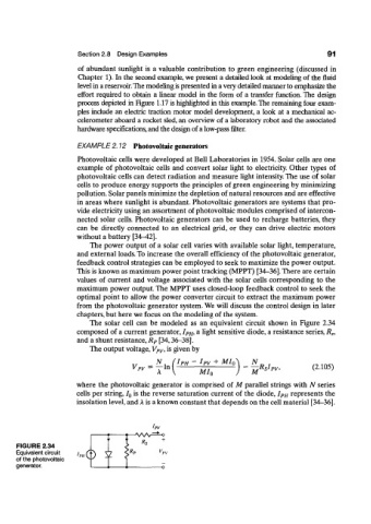
The solar cell can be modeled as an equivalent circuit shown in Figure 2.34
composed of a current generator, I PH, a light sensitive diode, a resistance series, R s,
and a shunt resistance, R P [34,36-38].
The output voltage, V PV, is given by
IPH ~ hv + MI Q
Vpv = — In MRshv, (2.105)
MIn
where the photovoltaic generator is comprised of M parallel strings with N series
cells per string, I Q is the reverse saturation current of the diode, I PH represents the
insolation level, and A is a known constant that depends on the cell material [34-36].
-AA/V
+
FIGURE 2.34
Equivalent circuit i
of the photovoltaic &>
generator.