
Page 116 - Modern Control Systems
P. 116
90 Chapter 2 Mathematical Models of Systems
R(s)Q
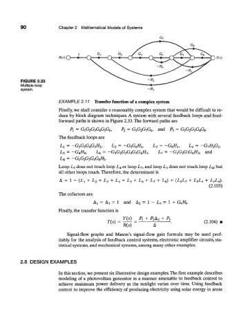
FIGURE 2.33
Multiple-loop
system. -H,
EXAMPLE 2.11 Transfer function of a complex system
Finally, we shall consider a reasonably complex system that would be difficult to re-
duce by block diagram techniques. A system with several feedback loops and feed-
forward paths is shown in Figure 2.33. The forward paths are
P\ = G1G2G3G4G5G6, P 2 — G1G2G7G6, and /¾ = G1G2G3G4G8.
The feedback loops are
L\ = — G2G3G4G5H2, L 2 = —Gsp^Hi, L 3 = -G 8 /ii, L 4 = -G-jH 2G 2,
L5 = —G4H4, L 6 = -G iG 2G^G4G$G^H ?„ L 7 = —GiGiGqG^H^,, and
Lg = —GiGiG^G^G^H^.
Loop L 5 does not touch loop L 4 or loop L 7 , and loop L 3 does not touch loop L 4; but
all other loops touch. Therefore, the determinant is
A = 1 - (Li + L 2 + L 3 + L 4 + L 5 + L 6 + L-, + L 8) + (L 5L 7 + L 5L 4 + L 3L 4).
(2.103)
The cofactors are
= = 1 and = 1 - L, = 1 +
A x A 3 A 2 GAH A 4 .
• 4 J 7
Finally, the transfer function is
Y(s) P r + P 2A 2 + P 2
T(s) = (2.104)
R(s)
Signal-flow graphs and Mason's signal-flow gain formula may be used prof-
itably for the analysis of feedback control systems, electronic amplifier circuits, sta-
tistical systems, and mechanical systems, among many other examples.
2.8 DESIGN EXAMPLES
In this section, we present six illustrative design examples. The first example describes
modeling of a photovoltaic generator in a manner amenable to feedback control to
achieve maximum power delivery as the sunlight varies over time. Using feedback
control to improve the efficiency of producing electricity using solar energy in areas