
Page 285 - Modular design for machine tools
P. 285
244 Engineering Design for Machine Tool Joints
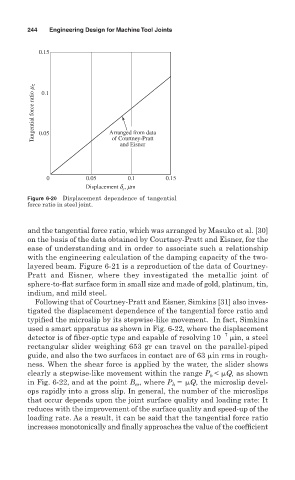
0.15
Tangential force ratio m τ 0.1
Arranged from data
0.05
of Courtney-Pratt
and Eisner
0 0.05 0.1 0.15
Displacement d , mm
s
Figure 6-20 Displacement dependence of tangential
force ratio in steel joint.
and the tangential force ratio, which was arranged by Masuko et al. [30]
on the basis of the data obtained by Courtney-Pratt and Eisner, for the
ease of understanding and in order to associate such a relationship
with the engineering calculation of the damping capacity of the two-
layered beam. Figure 6-21 is a reproduction of the data of Courtney-
Pratt and Eisner, where they investigated the metallic joint of
sphere-to-flat surface form in small size and made of gold, platinum, tin,
indium, and mild steel.
Following that of Courtney-Pratt and Eisner, Simkins [31] also inves-
tigated the displacement dependence of the tangential force ratio and
typified the microslip by its stepwise-like movement. In fact, Simkins
used a smart apparatus as shown in Fig. 6-22, where the displacement
detector is of fiber- optic type and capable of resolving 10 7 in, a steel
rectangular slider weighing 653 gr can travel on the parallel-piped
guide, and also the two surfaces in contact are of 63 in rms in rough-
ness. When the shear force is applied by the water, the slider shows
clearly a stepwise-like movement within the range P < Q, as shown
h
in Fig. 6-22, and at the point B , where P Q, the microslip devel-
h
cr
ops rapidly into a gross slip. In general, the number of the microslips
that occur depends upon the joint surface quality and loading rate: It
reduces with the improvement of the surface quality and speed-up of the
loading rate. As a result, it can be said that the tangential force ratio
increases monotonically and finally approaches the value of the coefficient