
Page 289 - Modular design for machine tools
P. 289
248 Engineering Design for Machine Tool Joints
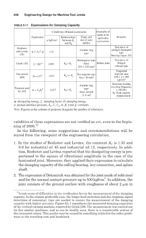
TABLE 6-11 Expressions for Damping Capacity
Conditions obtained expressions Examples of
joints to be
Expression Relationships Shape and applicable Remarks
p kgf/cm 2 between K j size of joint expressions
and K 0 surface
Test piece of
Reshetov
3
and Levina ψ = A C / √ p <15 Annular ring multiple-laminated
type
[38] type Interface layer: Oil
Rectangular type Test piece of
Groth [39] ζ = b p –g <100 K < K j Area: Bolted joint flanged
0
210 × 210 mm 2 column type
Tangential
Dekoninck K >> K Rectangular type load per area
D = Ct m <523 0 j
[40] Area: 40 mm 2 100 < t < 300
kgf/cm 2
Torsional loading
Annular ring
Tsutsumi and c type (exciting frequency
ψ = C q <12.7 K > K < 100 Hz)
Ito [41] a p 0 j Area: around
q p : Peak angular
11.4 cm 2 displacement
ψ: dissipating energy, z : damping factor, D: damping energy,
p: normal interface pressure, A , C, C , m, b, g and c: constants
C
a
Note: Figures in the column of proposer designate the number of references.
validities of these expressions are not verified as yet, even in the begin-
ning of 2000. 13
In the following, some suggestions and recommendations will be
stated from the viewpoint of the engineering calculation.
1. In the studies of Reshetov and Levina, the constant A is 1.35 and
C
0.9 for industrial oil 45 and industrial oil 12, respectively. In addi-
tion, Reshetov and Levina reported that the dissipating energy is pro-
portional to the square of vibrational amplitude in the case of the
laminated joint. Moreover, they applied their expression to calculate
the damping capacity of the rolling bearing, key connection, and spline
shaft.
2. The expression of Dekoninck was obtained for the joint made of mild steel
2
and for the normal contact pressure up to 500 kgf/cm . In addition, the
joint consists of the ground surface with roughness of about 2 min
13
A root cause of difficulties in the verification lies in the measurement of the damping
capacity. In the utmost preferable case, the larger load excitation and due response signal
detections of noncontact type are needed to ensure the measurement of the damping
capacity with higher accuracy. Figure 6A-1 reproduces the measured damping capacities
of the vertical turning machine reported by Groth [39]. The measurement was carried out
for five similar machines, and as can be readily seen, there is a considerable scatter of
the measured values. This scatter may be caused by something related to the roller guide-
ways at the traveling ram and headstock.