
Page 287 - Modular design for machine tools
P. 287
246 Engineering Design for Machine Tool Joints
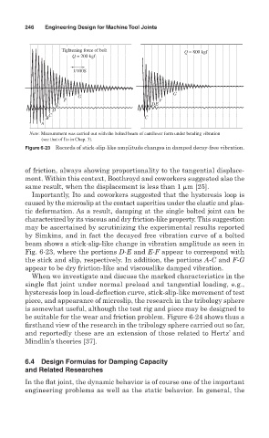
Tightening force of bolt Q = 800 kgf
Q = 200 kgf
1/100S
G
G
F F
E DE
D
C
B C
A
Note: Measurement was carried out with the bolted beam of cantilever form under bending vibration
(see that of Ito in Chap. 3).
Figure 6-23 Records of stick-slip-like amplitude changes in damped decay-free vibration.
of friction, always showing proportionality to the tangential displace-
ment. Within this context, Boothroyd and coworkers suggested also the
same result, when the displacement is less than 1 m [25].
Importantly, Ito and coworkers suggested that the hysteresis loop is
caused by the microslip at the contact asperities under the elastic and plas-
tic deformation. As a result, damping at the single bolted joint can be
characterized by its viscous and dry friction-like property. This suggestion
may be ascertained by scrutinizing the experimental results reported
by Simkins, and in fact the decayed free vibration curve of a bolted
beam shows a stick-slip-like change in vibration amplitude as seen in
Fig. 6-23, where the portions D-E and E-F appear to correspond with
the stick and slip, respectively. In addition, the portions A-C and F-G
appear to be dry friction-like and viscouslike damped vibration.
When we investigate and discuss the marked characteristics in the
single flat joint under normal preload and tangential loading, e.g.,
hysteresis loop in load-deflection curve, stick-slip-like movement of test
piece, and appearance of microslip, the research in the tribology sphere
is somewhat useful, although the test rig and piece may be designed to
be suitable for the wear and friction problem. Figure 6-24 shows thus a
firsthand view of the research in the tribology sphere carried out so far,
and reportedly these are an extension of those related to Hertz’ and
Mindlin’s theories [37].
6.4 Design Formulas for Damping Capacity
and Related Researches
In the flat joint, the dynamic behavior is of course one of the important
engineering problems as well as the static behavior. In general, the