
Page 291 - Modular design for machine tools
P. 291
250 Engineering Design for Machine Tool Joints
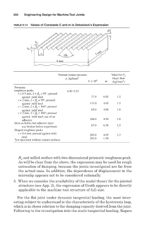
TABLE 6-13 Values of Constants C and m in Dekoninck’s Expression
H
b 0
h 0
s 5 mm
2b 0
4 mm
Normal contact pressure Valid for P t
p, kgf/mm 2 larger than
2
C × 10 6 m (kgf/mm )
Prismatic
roughness peaks 4.80–5.23
s = 0.5 mm, 2 × b = 90°, pressed
0
against mild steel 27.9 6.85 1.5
s = 2 mm, 2 × b = 90°, pressed
0
against mild steel 115.0 4.65 1.5
s = 2 mm, 2 × b = 160°, pressed
0
against mild steel 65.0 4.86 1.8
s = 2 mm, 2 × b = 160°, pressed
0
against mild steel; use of an
166.0 4.90 1.0
adhesive
Idem as before but adhesive layer
67.0 6.56 1.5
was broken before experiment
Shaped roughness peaks
s = 0.6 mm, pressed against mild
263.0 4.05 1.3
steel
Test specimen without contact surfaces 201.0 1.99
R and milled surface with two-dimensional prismatic roughness peak.
a
As will be clear from the above, the expression may be used for rough
estimation of damping, because the joints investigated are far from
the actual ones. In addition, the dependence of displacement in the
microslip appears not to be considered rationally.
3. When we consider the availability of the model theory for the jointed
structure (see App. 2), the expression of Groth appears to be directly
applicable to the machine tool structure of full-size.
For the flat joint under dynamic tangential loading, the most inter-
esting subject to understand is the characteristic of the hysteresis loop,
which is in closer relation to the damping capacity derived from the joint.
Following to the investigation into the static tangential loading, Rogers