
Page 295 - Modular design for machine tools
P. 295
254 Engineering Design for Machine Tool Joints
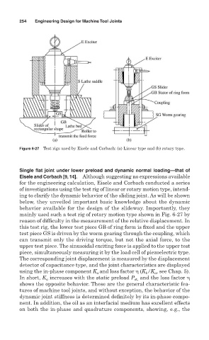
Figure 6-27 Test rigs used by Eisele and Corbach: (a) Linear type and (b) rotary type.
Single flat joint under lower preload and dynamic normal loading—that of
Eisele and Corbach [9, 14]. Although suggesting no expressions available
for the engineering calculation, Eisele and Corbach conducted a series
of investigations using the test rig of linear or rotary motion type, intend-
ing to clarify the dynamic behavior of the sliding joint. As will be shown
below, they unveiled important basic knowledge about the dynamic
behavior available for the design of the slideway. Importantly, they
mainly used such a test rig of rotary motion type shown in Fig. 6-27 by
reason of difficulty in the measurement of the relative displacement. In
this test rig, the lower test piece GB of ring form is fixed and the upper
test piece GS is driven by the worm gearing through the coupling, which
can transmit only the driving torque, but not the axial force, to the
upper test piece. The sinusoidal exciting force is applied to the upper test
piece, simultaneously measuring it by the load cell of piezoelectric type.
The corresponding joint displacement is measured by the displacement
detector of capacitance type, and the joint characteristics are displayed
using the in-phase component K and loss factor (K /K , see Chap. 5).
a
b
a
In short, K increases with the static preload P st, and the loss factor
a
shows the opposite behavior. These are the general characteristic fea-
tures of machine tool joints, and without exception, the behavior of the
dynamic joint stiffness is determined definitely by its in-phase compo-
nent. In addition, the oil as an interfacial medium has excellent effects
on both the in-phase and quadrature components, showing, e.g., the