
Page 172 - Book Hosokawa Nanoparticle Technology Handbook
P. 172
FUNDAMENTALS CH. 3 CHARACTERISTICS AND BEHAVIOR OF NANOPARTICLES AND ITS DISPERSION SYSTEMS
forces between surfaces can be obtained from the dis- dependence of an attractive force by varying the
placement of the spring that is connected to one of two spring constant and finding the distance where jump-
opposing surfaces. Sequentially, the separation dis- in occurs [7]. It is also possible to estimate the adhe-
tance between surfaces can be varied from submicron- sive force, which is the force necessary to separate the
meters to the adhesive contact. The surface jumps-in to surfaces in adhesive contact.
the contact when the gradient of the attractive force, The force measurement system could be divided
dF/dD, exceeds the spring constant (K), dF/dD K into two parts. One is a main chamber (Fig. 3.5.18)
(Fig. 3.5.19). It is possible to investigate the distance that consists of a surface driver (distance controller)
and a spring. The driver has a high resolution for vary-
ing the separation between two surfaces. Another part
is an optical interferometry system (Fig. 3.5.20) to
precisely measure the separation distance between
surfaces.
1. Main device: In a narrow sense, this unit is
called as the surface forces apparatus. This
instrument is commercially available. Mark 4 is
marketed from Australian National University
and SFA2000 can be purchased from Surface
LLC (USA). These apparatus are originated
from the prototype developed by Tabor,
Winterton, and Israelachvili. Construction of a
machine by oneself is also possible.
2. Optical system and distance determination: The
optical system needs to be set up by the opera-
tor. White light source (halogen lamp) is used.
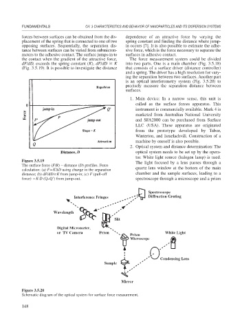
Figure 3.5.19 The light focused by a lens passes through a
The surface force (F/R) – distance (D) profiles. Force
calculation: (a) F K D using change in the separation quartz lens window at the bottom of the main
distance; (b) dF/dD K from jump-in; (c) F (pull-off chamber and the sample surfaces, leading to a
force) K·D (Q–Q ) from jump-out. spectroscope through a microscope and a prism
Figure 3.5.20
Schematic diagram of the optical system for surface force measurement.
148