
Page 174 - Book Hosokawa Nanoparticle Technology Handbook
P. 174
FUNDAMENTALS CH. 3 CHARACTERISTICS AND BEHAVIOR OF NANOPARTICLES AND ITS DISPERSION SYSTEMS
Figure 3.5.22
Schematic drawing of the atomic force microscope.
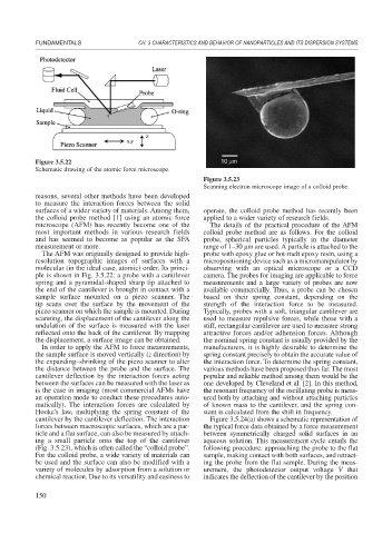
Figure 3.5.23
Scanning electron microscope image of a colloid probe.
reasons, several other methods have been developed
to measure the interaction forces between the solid
surfaces of a wider variety of materials. Among them, operate, the colloid probe method has recently been
the colloid probe method [1] using an atomic force applied to a wider variety of research fields.
microscope (AFM) has recently become one of the The details of the practical procedure of the AFM
most important methods in various research fields colloid probe method are as follows. For the colloid
and has seemed to become as popular as the SFA probe, spherical particles typically in the diameter
measurement or more. range of 1–30 m are used. A particle is attached to the
The AFM was originally designed to provide high- probe with epoxy glue or hot-melt epoxy resin, using a
resolution topographic images of surfaces with a micropositioning device such as a micromanipulator by
molecular (in the ideal case, atomic) order. Its princi- observing with an optical microscope or a CCD
ple is shown in Fig. 3.5.22: a probe with a cantilever camera. The probes for imaging are applicable to force
spring and a pyramidal-shaped sharp tip attached to measurements and a large variety of probes are now
the end of the cantilever is brought in contact with a available commercially. Thus, a probe can be chosen
sample surface mounted on a piezo scanner. The based on their spring constant, depending on the
tip scans over the surface by the movement of the strength of the interaction force to be measured.
piezo scanner on which the sample is mounted. During Typically, probes with a soft, triangular cantilever are
scanning, the displacement of the cantilever along the used to measure repulsive forces, while those with a
undulation of the surface is measured with the laser stiff, rectangular cantilever are used to measure strong
reflected onto the back of the cantilever. By mapping attractive forces and/or adhension forces. Although
the displacement, a surface image can be obtained. the nominal spring constant is usually provided by the
In order to apply the AFM to force measurements, manufacturers, it is highly desirable to determine the
the sample surface is moved vertically (z direction) by spring constant precisely to obtain the accurate value of
the expanding–shrinking of the piezo scanner to alter the interaction force. To determine the spring constant,
the distance between the probe and the surface. The various methods have been proposed thus far. The most
cantilever deflection by the interaction forces acting popular and reliable method among them would be the
between the surfaces can be measured with the laser as one developed by Cleveland et al. [2]. In this method,
is the case in imaging (most commercial AFMs have the resonant frequency of the oscillating probe is meas-
an operation mode to conduct these procedures auto- ured both by attaching and without attaching particles
matically). The interaction forces are calculated by of known mass to the cantilever, and the spring con-
Hooke’s law, multiplying the spring constant of the stant is calculated from the shift in frequency.
cantilever by the cantilever deflection. The interaction Figure 3.5.24(a) shows a schematic representation of
forces between macroscopic surfaces, which are a par- the typical force data obtained by a force measurement
ticle and a flat surface, can also be measured by attach- between symmetrically charged solid surfaces in an
ing a small particle onto the top of the cantilever aqueous solution. This measurement cycle entails the
(Fig. 3.5.23), which is often called the “colloid probe”. following procedure: approaching the probe to the flat
For the colloid probe, a wide variety of materials can sample, making contact with both surfaces, and retract-
be used and the surface can also be modified with a ing the probe from the flat sample. During the meas-
variety of molecules by adsorption from a solution or urement, the photodetector output voltage V that
chemical reaction. Due to its versatility and easiness to indicates the deflection of the cantilever by the position
150