
Page 568 - Book Hosokawa Nanoparticle Technology Handbook
P. 568
APPLICATIONS 28 DEVELOPMENT OF FUEL CELLS
lower-temperature operating SOFC, and such develop- The voltage loss consists of the IR loss of cell com-
ments are the present trends in Europe and Japan. ponents, polarization loss of both electrodes and the
These developments have aimed to decrease the SOFC Nernst loss. The Nernst loss means OCV decrease by
operating temperature to 800ºC or less. Further devel- the concentration change of fuel and air during power
opments aiming at the operation temperature of 600ºC generation (see equation (28.1)). In Fig. 28.2, IR loss,
or less have also begun. The lower operating tempera- polarization loss and Nernst loss are subtracted from
ture expands the applicability of the material for the OCV, and the terminal voltage of the cell is calcu-
SOFC and enables application of metallic materials lated. Therefore, the power density of the cell
such as stainless steel and also a rapid start and stop. increases with a decrease in voltage loss, and how
much IR loss and polarization loss are reduced leads
to the improvement of the power generation effi-
2. Development of high-performance solid oxide fuel
ciency of fuel cells. In SOFC, the development of the
cells using nanoparticle technology high ion-conductive material as an electrolyte and
making a thin-film electrolyte have been tried to
Open circuit voltage (OCV) of the fuel cell depends on decrease the IR loss. Moreover, the development of
some parameters such as kinds of fuels and oxidants as high-activity and conductive electrode materials and
well as operation conditions (temperature, pressure their microstructure control have been attempted to
and concentration of fuel and oxidant). Theoretical decrease the polarization loss.
OCV (E) can be calculated from the Gibbs free energy For standard SOFC component materials (see
of standard formation ( G ) and concentration of fuel Fig. 28.1), the lower temperature (700ºC) operation of
0
and oxidant, when hydrogen is used as a fuel and air as SOFC has been achieved by development of an anode-
an oxidant, by the following equation: supported thin-electrolyte cell with nanopowder pro-
1
In the case of reaction H O H O: cessing and by microstructure control of electrodes
2
2
2
2
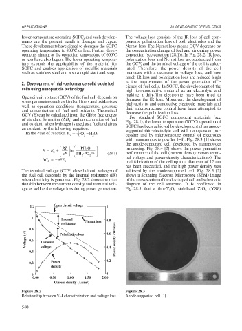
with nanocomposite powder 1–4). Fig. 28.3 [1] shows
the anode-supported cell developed by nanopowder
⎛ RT ⎞ ⎛ PH O ⎞ processing. Fig. 28.4 [2] shows the power generation
ln
E E ⎜ ⎟ ⎜ ⎜ 2 12 ⎟ ⎟
0
⎝ nF ⎠ ⎝ PH PO 2 ⎠ (28.1) performance of the cell (current density versus termi-
2
G nFE nal voltage and power-density characterizations). The
0 0 trial fabrication of the cell up to a diameter of 12 cm
has been succeeded, and the high power density was
The terminal voltage (CCV: closed circuit voltage) of achieved by the anode-supported cell. Fig. 28.5 [2]
the fuel cell descends by the internal resistance (IR) shows a Scanning Electron Microscope (SEM) image
when electricity is generated. Fig. 28.2 shows the rela- of the cross section of the developed cell and schematic
tionship between the current density and terminal volt- diagram of the cell structure. It is confirmed in
age as well as the voltage loss during power generation. Fig. 28.5 that a thin-Y O stabilized ZrO (YSZ)
2
3
2
1.2 Open circuit voltage 1
1 Internal
Nernst loss 0.8
resistance
0.8 0.6
Voltage (V) 0.6 Terminal Polarization loss Power density (Wcm -2 )
0.4 voltage 0.4
0.2 Power 0.2
density
0 0
0.00 0.50 1.00 1.50 2.00
2
Current density (A/cm )
Figure 28.2 Figure 28.3
Relationship between V–I characterization and voltage loss. Anode-supported cell [1].
540