
Page 95 - Book Hosokawa Nanoparticle Technology Handbook
P. 95
2.3 PARTICLE SHAPE FUNDAMENTALS
The grinding operation is a very effective technique [7] T. Yokoyama, Y. Taniyama, G. Jinbo and Q. Zhao: J. Soc.
not only to break solid particles but also to disperse Powder Technol., Jpn., 28, 751–758 (1991).
nanoparticle agglomerates. For example, a useful mill
can disperse nanoparticle agglomerates generated in gas 2.3 Particle shape
or liquid phase in the dry state. As to dispersing nanopar-
ticles in slurry, liquid jet mills are also as effective as the
media agitation mills and planetary ball mills. Grinding 2.3.1. Gas-phase process
plays an important role both in the conventional particle
production and nanoparticle production systems. Evaluation and control of the morphology of the par-
ticles produced by chemical vapor deposition (CVD)
and spray methods in the gas phase are more difficult
References
than those prepared by liquid-phase methods. Aerosol
particles synthesized via aerosol routes, including
[1] S. Morohashi, Y. Sawahara: J. Soc. Mater. Sci., Jpn., 22,
CVD and spray methods, are either droplets (liquid
689–692 (1973).
particles) or solid particles. In the case of the droplets,
[2] Hosokawa Micron Corporation Micromeritics
the morphology is typically spherical. In contrast, in
Laboratory: Mechanofusion, p. 46 (1989).
the case of solid particles, the morphology is strongly
[3] K. Kugimiya: The Micromeritics, 36, 177–180 (1992). dependent on the deposition process of crystalline
[4] H. Yoden, N. Ito: J. Soc. Powder Technol., Jpn., 41, particles from gas and liquid phases.
457–464 (2004).
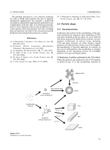
[5] M. Inkyo, T. Tahara: J. Soc. Powder Technol., Jpn., 41, (1) Morphology of particles synthesized by the CVD method
578–585 (2004). When the particles are produced by the CVD method,
[6] T. Ishii: Powder Sci. Eng., 37(8), 51–57 (2005). as shown in Fig. 2.3.1, the morphology depends on
agglomeration
sintering
high concentration
sphere
amorphous
at low temperature
condensable
material cube
I a
I b
I a = I b = I c
I c
I a > I b = I c
fiber
crystalline
at high temperature
I a = I b > I c
plates
Figure 2.3.1
Variation of crystal structure.
71