
Page 120 - Neural Network Modeling and Identification of Dynamical Systems
P. 120
3.4 ANN-BASED CONTROL OF DYNAMICAL SYSTEMS 109
carried out regarding a maneuverable Su-17 air-
craft [73]. (See Figs. 3.7 and 3.8.)
The first operation that needed to be done to
perform these experiments was the generation
of a training set. It is a pair of input–output ma-
trices, the first of which specifies the set of all
possible values of the aircraft variables, and the
second is the change of the corresponding vari-
ables in a given time interval, assumed to be
0.01 sec.
The values of the parameters considered as
constants in the model (3.23) were chosen as fol-
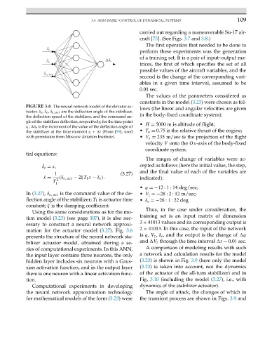
FIGURE 3.6 The neural network model of the elevator ac- lows (the linear and angular velocities are given
tuator. δ e , ˙ δ e , δ e, act are the deflection angle of the stabilizer,
the deflection speed of the stabilizer, and the command an- in the body-fixed coordinate system):
gle of the stabilizer deflection, respectively, for the time point • H = 5000 m is altitude of flight;
t i ; δ e is the increment of the value of the deflection angle of
the stabilizer at the time moment t i + t (From [99], used • T a = 0.75 is the relative thrust of the engine;
with permission from Moscow Aviation Institute). • V x = 235 m/sec is the projection of the flight
velocity V onto the Ox-axis of the body-fixed
coordinate system.
tial equations:
The ranges of change of variables were ac-
˙ = x, cepted as follows (here the initial value, the step,
δ e
and the final value of each of the variables are
1 (3.27)
˙ x = 2 (δ e, act − 2ξT 1 x − δ e ). indicated):
T
1
• q =−12 : 1 : 14 deg/sec;
In (3.27), δ e, act is the command value of the de- • V z =−28 : 2 : 12 m/sec;
flection angle of the stabilizer; T 1 is actuator time • δ e =−26 : 1 : 22 deg.
constant; ξ is the damping coefficient.
Thus, in the case under consideration, the
Using the same considerations as for the mo-
tion model (3.23) (see page 107), it is also nec- training set is an input matrix of dimension
3 × 41013 values and its corresponding output is
essary to construct a neural network approxi-
mation for the actuator model (3.27). Fig. 3.6 2 × 41013. In this case, the input of the network
presents the structure of the neural network sta- is q, V z , δ e , and the output is the change of q
bilizer actuator model, obtained during a se- and V z through the time interval t = 0.01 sec.
ries of computational experiments. In this ANN, A comparison of modeling results with such
the input layer contains three neurons, the only a network and calculation results for the model
hidden layer includes six neurons with a Gaus- (3.23) is shown in Fig. 3.9 (here only the model
sian activation function, and in the output layer (3.23) is taken into account, not the dynamics
there is one neuron with a linear activation func- of the actuator of the all-turn stabilizer) and in
tion. Fig. 3.10 (including the model (3.27), i.e., with
Computational experiments in developing dynamics of the stabilizer actuator).
the neural network approximation technology The angle of attack, the changes of which in
for mathematical models of the form (3.23)were the transient process are shown in Figs. 3.9 and