
Page 390 - Offshore Electrical Engineering Manual
P. 390
Motor Commissioning Tests 377
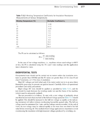
Table 7.5.2 Winding Temperature Coefficients for Insulation Resistance
Measurements at Various Temperatures
Winding Temperature (°C) Multiplier Coefficient k t
0 0.06
10 0.12
20 0.25
30 0.5
40 1.0
50 2.0
60 4.0
70 8.0
80 16.0
90 32.0
100 64.0
The PI can be calculated as follows:
10 ‐ min reading
PI =
1 ‐ min reading
In the case of low-voltage machines, i.e., machines whose rated voltage is 600 V
or less, the PI is calculated using the 30-s and 1-min readings and the application
time is limited to 1 min.
OVERPOTENTIAL TESTS
Overpotential tests should not be carried out on motors unless the insulation resis-
tance is greater than 100 MΩ and the PI values are greater than 2.0 for class B and
class F insulation, or 1.5 for class A insulation.
High DC voltages are both lethal and, if the motor under test is in an area where
flammable gases may be present, an ignition hazard. Carefully follow all operational
procedures and safety precautions.
High-voltage DC tests should be applied as specified in Table 7.5.3, and the
test should be made between the windings under test and the frame of the machine
(which must be adequately earthed).
The test procedure is as follows. To start with, a test voltage of preferably about
one-third but not more than one-half of the full test voltage quoted in Table 7.5.3 should
be applied. This should be increased to the full test voltage as rapidly as the indicat-
ing instrument will allow without overshooting beyond the quoted value. The full test
voltage must be maintained for 1 min, and the leakage current recorded. At the end of
1 min, the test voltage must be reduced rapidly to not more than one-third of its full
value before switching off. This method of test voltage application is important to avoid
overstressing the insulation with high transient voltages produced by switching, etc.