
Page 183 - Organic Electronics in Sensors and Biotechnology
P. 183
160 Cha pte r F o u r
1.E–05
1.E–06
1.E–07
I ds (A)
1.E–08
1.E–09
1.E–10
0 500 1000 1500
Time (s)
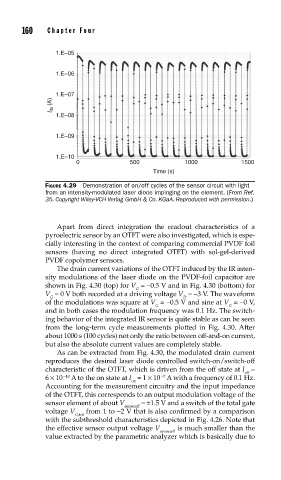
FIGURE 4.29 Demonstration of on/off cycles of the sensor circuit with light
from an intensity-modulated laser diode impinging on the element. (From Ref.
35. Copyright Wiley-VCH Verlag GmbH & Co. KGaA. Reproduced with permission.)
Apart from direct integration the readout characteristics of a
pyroelectric sensor by an OTFT were also investigated, which is espe-
cially interesting in the context of comparing commercial PVDF foil
sensors (having no direct integrated OTFT) with sol-gel-derived
PVDF copolymer sensors.
The drain current variations of the OTFT induced by the IR inten-
sity modulations of the laser diode on the PVDF-foil capacitor are
shown in Fig. 4.30 (top) for V = −0.5 V and in Fig. 4.30 (bottom) for
G
V = 0 V both recorded at a driving voltage V = −3 V. The waveform
G D
of the modulations was square at V = −0.5 V and sine at V = −0 V,
G G
and in both cases the modulation frequency was 0.1 Hz. The switch-
ing behavior of the integrated IR sensor is quite stable as can be seen
from the long-term cycle measurements plotted in Fig. 4.30. After
about 1000 s (100 cycles) not only the ratio between off-and-on current,
but also the absolute current values are completely stable.
As can be extracted from Fig. 4.30, the modulated drain current
reproduces the desired laser diode controlled switch-on/switch-off
characteristic of the OTFT, which is driven from the off state at I =
off
6 × 10 −10 A to the on state at I = 1 × 10 A with a frequency of 0.1 Hz.
−7
on
Accounting for the measurement circuitry and the input impedance
of the OTFT, this corresponds to an output modulation voltage of the
sensor element of about V = ±1.5 V and a switch of the total gate
sense;eff
voltage V from 1 to −2 V that is also confirmed by a comparison
G;tot
with the subthreshold characteristics depicted in Fig. 4.26. Note that
the effective sensor output voltage V is much smaller than the
sense;eff
value extracted by the parametric analyzer which is basically due to