
Page 182 - Organic Electronics in Sensors and Biotechnology
P. 182
Integrated Pyr oelectric Sensors 159
Pentacene
Source Drain
Nanocomposite
gate dielectric
Laser spot
Top Gate
electrode
P(VDT-TrFE) Flexible PET substrate
(a)
(b) (c)
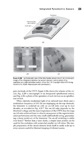
FIGURE 4.28 (a) Schematic view of the fully fl exible sensor circuit, (b) microscopic
image of the integrated optothermal sensor element, and (c) photo of its
operation as a light-activated switch. (From Ref. 35. Copyright Wiley-VCH Verlag
GmbH & Co. KGaA. Reproduced with permission.)
gate electrode of the OTFT. Figure 4.28a shows the scheme of the cir-
cuit, Fig. 4.28b a micrograph of an integrated optothermal sensor,
and Fig. 4.28c a photo of the operation of such devices as an optother-
mal switch.
When intensity-modulated light of an infrared laser diode and a
modulation frequency of 0.01 Hz are impinging on the top electrode,
the transistor is switched on with an on/off ratio over up to four
decades, as revealed in Fig. 4.29. The on/off ratio depends on the
35
threshold voltage and the input impedance of the OTFT; thus the large
on/off ratio achieved here is a direct consequence of the superior tran-
sistor performance and the very small subthreshold swing, guarantee-
ing a sharp switch-on of the transistor. The on-off switching is stable
35
over hours. Rather than a laser diode, a simple laser pointer can be
used for the excitation with somewhat smaller on/off ratios. The sim-
ple preparation of the circuit element lends itself to easily scale up to
array sensors useful for thermal imaging of infrared scenes.