
Page 432 - Orlicky's Material Requirements Planning
P. 432
410 PART 4 Looking Backward and Forward
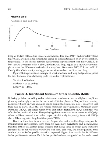
FIGURE 24-3
Purchased-part lead time.
Number of Parts
10 20 30 40 50 60
Lead Time Days
Chapter 23, two of these lead times, manufacturing lead time (MLT) and cumulative lead
time (CLT), are most often unrealistic, either an underestimation or an overestimation,
respectively. To this extent, actively synchronized replenishment lead time (ASRLT) is
best used to determine what is short, medium, and long. Figure 24-4 provides an exam-
ple of what the difference in distribution may look like among MLT, CLT, and ASRLT.
Clearly, this affects what planning personnel view as short, medium, and long.
Figure 24-5 represents an example of short, medium, and long designation against
the distribution of manufacturing parts chosen for replenishment.
Short 1 to 10 days.
Medium 11 to 25 days.
Long 26 days.
Factor 4: Significant Minimum Order Quantity (MOQ)
Ordering policies, including order minimums, maximums, and multiples, complicate
planning and supply scenarios but are a fact of life for planners. Many of these ordering
policies are based on valid data and sound assumption; some are not. It is a given that
there will be parts/SKUs that do require minimum order quantities. Minimum order
quantities (MOQs) can affect buffer levels and zones. Significant MOQs definitely will
affect buffer levels and zones. The qualifying characteristics of what makes an MOQ sig-
nificant will be examined later in this chapter. Additionally, frequently, times with MOQs
also will be designated long-lead-time parts/SKUs.
Based on these four factors, there are 54 potential buffer profiles. Depending on the
manufacturing environment, there could be even more derivations and permutations
than this. If there is a certain global attribute that makes sense by which parts should be
grouped that is not related to variability, lead time, part type, and order quantity, then
another type of buffer profile should be explored. Figure 24-6 details the 54 different
buffer profile combinations. Each buffer profile has been designated with a code based