
Page 58 - Phase Space Optics Fundamentals and Applications
P. 58
Wigner Distribution in Optics 39
u axis. The -rotated smoothed interferogram P (x, u; w, z) for the
f
optimal fractional angle =−49 is presented in Fig. 1.6c for a rect-
◦
angular window with T = 9 and in Fig. 1.6d for a Hann(ing) window
with T = 15. We can see that as a consequence of the high concentra-
tion of the components along the optimal fractional angle, we almost
achieved the goal of getting the auto-terms of the Wigner distribution
without any cross-terms.
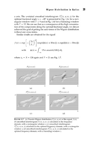
Similar results are obtained for the signal
8
3x
f (x) = exp − (exp{i[ (x) + 50 x]}+ exp{i[ (x) − 50 x]})
x o
x
with (x) = 15 arcsinh(100 ) d ,
−∞
where x o = X = 128 again and T = 21 see Fig. 1.7.
P f (x,u;w) P f (x,u;w,z)
x x
u u
(a) (b)
γ
γ
P f (x,u;w,z) P f (x,u;w,z)
x x
u u
(c) (d)
FIGURE 1.7 (a) Pseudo-Wigner distribution P f (x, u; w) of the signal f (x);
(b) smoothed interferogram P f (x, u; w, z) calculated in the frequency
domain, with a rectangular window z;(c) smoothed interferogram
P (x, u; w, z) calculated in the optimal frequency domain, with a rectangular
f
window z;(d) smoothed interferogram P (x, u; w, z) calculated in the
f
optimal frequency domain, with a Hann(ing) window z.