
Page 120 - Phase-Locked Loops Design, Simulation, and Applications
P. 120
MIXED-SIGNAL PLL ANALYSIS Ronald E. Best 78
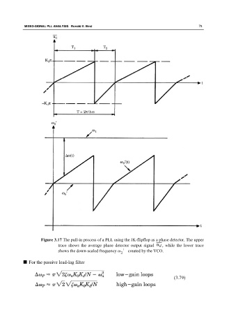
Figure 3.17 The pull-in process of a PLL using the JK-flipflop as a phase detector. The upper
trace shows the average phase detector output signal , while the lower trace
shows the down-scaled frequency ω ′ created by the VCO.
2
■ For the passive lead-lag filter
(3.79)