
Page 113 - Photoreactive Organic Thin Films
P. 113
ZOUHEIR SEfCKAT
values. The occurrence of anisotropy is indicative of photo-orientation of the
chromophores. The green-light-induced orientation of the chromophores
showed a dynamical behavior (not shown) similar to that of Figure 3.17. In
this experiment, the SP/PMMA samples were irradiated by unpolarized UV
light to the photo-stationary state, and linearly polarized green irradiation
followed. Spiropyran molecules degrade after successive irradiation cycles;
therefore, each photo-orientation experiment has been done on a different
previously nonirradiated sample so as to avoid degradation complications.
For high irradiation doses, higher than those reported in Figures 3.17 and
3.18, the evolution of the isotropic absorbance exhibits a reversal at the
photostationary state due to the degradation of the chromophores.
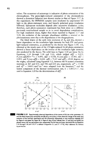
The fitted slopes of the early time evolution of A B and AA B showed a
linear dependence on the irradiation light intensity for both UV- and green-
light-induced orientation, as predicted by the theory (see Figure 3.18). l/S B
obtained at the steady state of the UV-light-induced A<-»B photo-orientation
showed a linear dependence on the inverse of the irradiation light intensity,
also predicted by the theory. The solid lines in Figure 3.18 are linear fits by
5
Equations 3.14 through 3.18 and 3.22, which yielded <£j| = 0.053,
3
6
B
P 2(cos<4f 3)P^ ^ = 0-493, 4>EA = 0.030, P 2(coso> ,g) = -0.345, c^l =
0.003, and F 2(cos <ugf) = 0.642. o»|g = 71.25 and a$3 = 29.24 degrees are
the angles, calculated using Equation 3.2, between the B isomer's transition
46
moments at 365 and 633, and 546 and 633 nm, respectively. ej = 11380
33
1
38
and eg = 3460 L moHcnT were adapted from the literature, and the
1
fastest component of the thermal isomerization rate, k = 0.00125 s" , was
used in Equation 3.20 for the determination of
(A) (B)
5
10' *1/F
o.o 0.5 1.0 1.5 2.0 2.5 3.0
120
F*icr
X'*10
FIGURE 3.18 Experimentally observed dependence of the inverse of (A) the order parameter, US,
and the fitted slopes, p(A) and p(AA), and (B) p(A N) and p(AA N), of the observed change of the early time
evolution of the isotropic absorbance and the anisotropy, respectively, on the irradiation intensity (UV
for Figure A and green for Figure B). In Figure A, the arrows indicate that I/S, and p(A) and p(AA), are
plotted versus the top and bottom axis, respectively. The full lines are linear theoretical fits by Equations
3.14 through 3.18, and 3.22; f is defined in Appendix 3.1; and X' = F'*A^. After reference 26, redrawn
by permission.