
Page 91 - Photoreactive Organic Thin Films
P. 91
ZOUHEIR SEKKAT
3.3.2. i Purely Polarized Transitions Symmetry
In the following discussion, A and B refer to the trans and cis isomers,
respectively. We assume that A— »B photoconversion occurs upon excitation of
a purely polarized transition with light linearly polarized along the laboratory
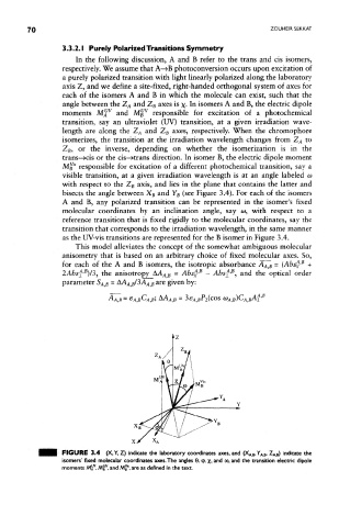
axis Z, and we define a site-fixed, right-handed orthogonal system of axes for
each of the isomers A and B in which the molecule can exist, such that the
angle between the Z A and Z B axes is x- In isomers A and B, the electric dipole
V V
moments M A and M B responsible for excitation of a photochemical
transition, say an ultraviolet (UV) transition, at a given irradiation wave-
length are along the Z A and Z B axes, respectively. When the chrornophore
isomerizes, the transition at the irradiation wavelength changes from Z A to
Z B, or the inverse, depending on whether the isomerization is in the
trans-»cis or the cis— Hrans direction. In isomer B, the electric dipole moment
S
MB' responsible for excitation of a different photochemical transition, say a
visible transition, at a given irradiation wavelength is at an angle labeled ca
with respect to the Z B axis, and lies in the plane that contains the latter and
bisects the angle between X B and Y B (see Figure 3.4). For each of the isomers
A and B, any polarized transition can be represented in the isomer's fixed
molecular coordinates by an inclination angle, say w, with respect to a
reference transition that is fixed rigidly to the molecular coordinates, say the
transition that corresponds to the irradiation wavelength, in the same manner
as the UV-vis transitions are represented for the B isomer in Figure 3.4.
This model alleviates the concept of the somewhat ambiguous molecular
anisornetry that is based on an arbitrary choice of fixed molecular axes. So,
B
for each of the A and B isomers, the isotropic absorbance A AfB ~ (Absf' +
E
>B
B
2Absf' }/3, the anisotropy_AA^ )S = Absf}' - Abs± , and the optical order
parameter S AjB = AA A)B/3 A A B are given by:
FIGURE 3.4 (X, Y, Z) indicate the laboratory coordinates axes, and (X A B, Y A B, Z^ B) indicate the
isomers' fixed molecular coordinates axes. The angles 0, <p, x> and o>, and the transition electric dtpole
moments Al^, M^, and Mjf*. are as defined in the text.