Page 183 - Practical Control Engineering a Guide for Engineers, Managers, and Practitioners
P. 183

158  Chapter  Six


                  2.5 r---~----r--~---r----r-----r-----,~----,
                          0
                   2     0,  •••••  ,  0   ••••   •  ,   ••••• '  •   •••  0   0   •••  0   ....   9  ....
                         ·1 o  Closed-loop roots PI  t ·  ·  ·  ·  ·  ·. ·
                                          0
                          0
                               0
                                     0
                  1.5
                         .  v  Closed-loop roots PID . : .  . ......  .
                   1
                                                .
                  0.5       •••  •   .  •  ••  0   ·'·  ••••  :   •  ••••• ••••
                                                •
                               :
                                                         v.
                                                       ··0·
                                                         -.;r
                 -0.5
                                                     0
                  -1                 0  ~   •   •   •   •   •   :  •   •   •   •   0   0   ••  •   0   •   •   •   •   • ••
                 -1.5                  •••• :  .  ••••  0   :  .  0   0   •   0   0   :  .  •
                  -2                              ···'····  6'
                  2                                       :
                 - :?14   -12   -10   -8   -6   -4   -2   0     2
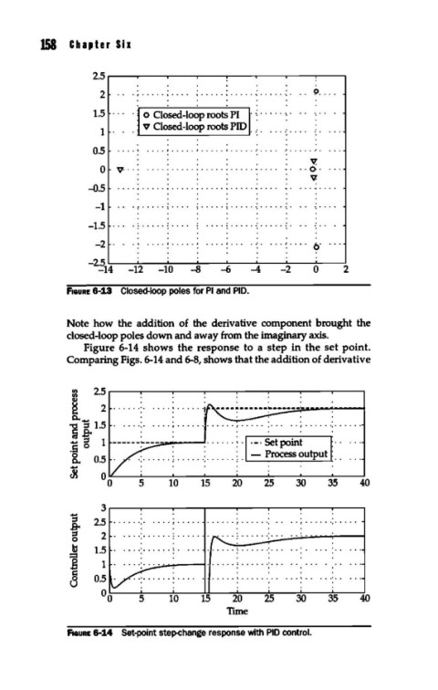
             fiGURE 6-:1.3  Closed-loop poles for PI and PID.
             Note how  the  addition  of the derivative  component brought  the
             closed-loop poles down and away from the imaginary axis.
                Figure 6-14  shows the response to  a  step in the set point.
             Comparing Figs. 6-14 and 6-8, shows that the addition of derivative


              :g   2.5 r---"""T""---r-----r---..-----r--.,....-----r------,
              ~    2  ......  •.
              a.. ....
              ~ =  1.5
              ~ t  1
              .s
              &.   0.5
                          5     10    15   20    25    30    35   40

                   3r---"""T""---r-----r---..-----r--.,....-----r------,
                                .           .           .    .
                  2.5  ..... ·.·   •••• :   •  •••••  0   ••  0.  ·: ••••• ••   •   ·:  •••  0   ••••••••
                   2
                  1.5   .....  0   ••••••••••••••••••••••••••
                   1                   ...............  .
                  0.5

                                10    15   20    25    30    35    40
                                          Tune

             fiGURE 6-14  Set-point step-change response with PID control.
   178   179   180   181   182   183   184   185   186   187   188