
Page 296 - Practical Power System and Protective Relays Commissioning
P. 296
290 Practical Power System and Protective Relays Commissioning
Worked example 2
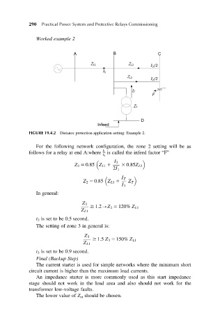
FIGURE 19.4.2 Distance protection application setting: Example 2.
For the following network configuration, the zone 2 setting will be as
follows for a relay at end A:where I 2 is called the infeed factor “F”
I 1
I 2
Z 2 5 0:85 Z L1 1 3 0:85Z L2
2I 1
I T
Z 2 5 0:85 Z L1 1 Z T
I 1
In general:
Z 2
$ 1:2-Z 2 5 120% Z L1
Z L1
t 2 is set to be 0.5 second.
The setting of zone 3 in general is:
Z 3
$ 1:5 Z 3 5 150% Z L1
Z L1
t 3 is set to be 0.9 second.
Final (Backup Step)
The current starter is used for simple networks where the minimum short
circuit current is higher than the maximum load currents.
An impedance starter is more commonly used as this start impedance
stage should not work in the load area and also should not work for the
transformer low-voltage faults.
The lower value of Z st should be chosen.