
Page 301 - Practical Power System and Protective Relays Commissioning
P. 301
Protection Relays Settings Chapter | 19 295
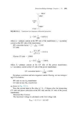
FIGURE 19.5.1 Transformer low-impedance differential protection.
1
i 1 5 219 5 0:876 A
250
where I 1 5 primary current at the HV side of the transformer; i 1 5 secondary
current at the HV side of the transformer.
HV correction factor 5 1 5 1 5 1:145
i 1 0:876
LV side:
25 3 10 3
I 1 5 p ffiffiffi 5 1312 A
3 3 11
Choose CT ratio 5 1300/1
1
i 2 5 1312 5 1:009A
1300
where I 2 5 primary current at the LV side of the power transformer;
i 2 5 secondary current at the LV side of the power transformer.
1
LV correction factor 5 5 0:991
1:009
For phase correction and zero-sequence current filtering, we use interpos-
ing CT as follows:
HV side we use Yy 0 transformer
LV side we use Yd 11 transformer
as shown in Fig. 19.5.2.
Now the current input to the relay is 1 A +0 degree after the interposing
CT ratio and phase correction at the HV side and the LV side of the power
transformer.
Minimum Bias Current
The maximum voltage is calculated at the low-voltage side.
V max 5 11 3 1:1 5 12:1kV