
Page 304 - Practical Power System and Protective Relays Commissioning
P. 304
298 Practical Power System and Protective Relays Commissioning
Tertiary side 11 kV side:
100 3 10 3
I 3 5 p ffiffiffi 5 5248:63 A
3 3 11
Choose CT 5 5000/1
5248:63
i 3 5 5 1:0497 A
5000
Tertiary side correction factor 5 1 5 0:952
1:0497
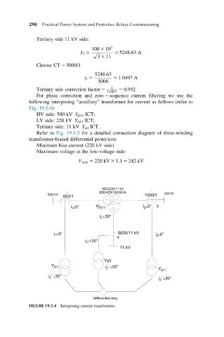
For phase correction and zero 5 sequence current filtering we use the
following interposing “auxiliary” transformer for current as follows (refer to
Fig. 19.5.4):
HV side: 500 kV Y d11 ICT;
LV side: 220 kV Y d11 ICT;
Tertiary side: 11 kV Y y0 ICT.
Refer to Fig. 19.5.5 for a detailed connection diagram of three-winding
transformer-biased differential protection.
Minimum bias current (220 kV side)
Maximum voltage at the low-voltage side:
V max 5 220 kV 3 1:1 5 242 kV
FIGURE 19.5.4 Interposing current transformers.