
Page 307 - Practical Power System and Protective Relays Commissioning
P. 307
Protection Relays Settings Chapter | 19 301
19.5.3 HIGH-IMPEDANCE DIFFERENTIAL PROTECTION
SETTING
19.5.3.1 Worked Example 1 (Fig. 19.5.7)
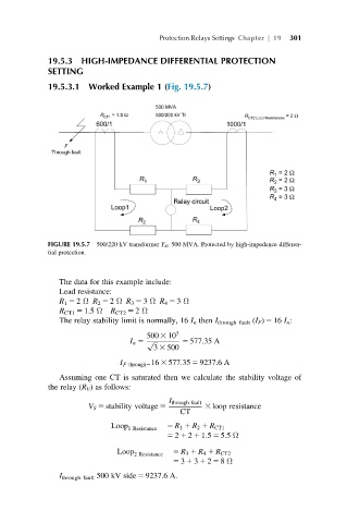
FIGURE 19.5.7 500/220 kV transformer Y d1 500 MVA. Protected by high-impedance differen-
tial protection.
The data for this example include:
Lead resistance:
R 1 5 2 Ω R 2 5 2 Ω R 3 5 3 Ω R 4 5 3 Ω
R CT1 5 1.5 Ω R CT2 5 2 Ω
The relay stability limit is normally, 16 I n then I through fault (I F ) 5 16 I n :
500 3 10 3
I n 5 p ffiffiffi 5 577:35 A
3 3 500
I F through5 16 3 577:35 5 9237:6A
Assuming one CT is saturated then we calculate the stability voltage of
the relay (R V ) as follows:
I through fault
V S 5 stability voltage 5 3 loop resistance
CT
Loop 1 Resistance 5 R 1 1 R 2 1 R CT1
5 2 1 2 1 1:5 5 5:5 Ω
Loop 2 Resistance 5 R 3 1 R 4 1 R CT2
5 3 1 3 1 2 5 8 Ω
I through fault 500 kV side 5 9237.6 A.