Page 311 - Practical Power System and Protective Relays Commissioning
P. 311

Protection Relays Settings Chapter | 19  305


                                     16 3 500 3 10 3
                                  5        p
                        V S2 LV side        ffiffiffi    ð R 3 1 R 4 1 R CT2 Þ
                                    1000 3  3 3 220
                                  5 20:994 3 1 3 1 2:5Þ
                                          ð
                                  5 20:994 8:5Þ 5 178:449 V
                                          ð
                For an autotransformer:
                I Neutral5 I LV side  I HV side
                                                    ð
                                     ð
                       V S neutral side  5 20:994   15:396Þ R 5 1 R 6 1 R CT3 Þ
                                          ð
                                   5 5:598 1:5 1 1:5 1 2:5Þ
                                   5 5:598 5:5Þ
                                         ð
                                   5 30:789 V
                Then, V S2 . V S1 . V S3 .
                Choose V s2 as V S 5 180 V.
                Use voltage relay 20 200 V with 20-V taps.
                Set V S 5 180 V, burden 5 1 VA.
                Then V K min should be 2V S .
                V K min 5 2 3 180 5 360 V.
                Use CT with V K 5 400 V ,a current relay with burden 5 500 Ω, and
             current 5 30 mA.
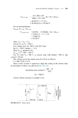
                The voltage across the current relay R I will be as follows:
                V 5 500 3 0.03 5 15 V
                Then a series resistor is required to adjust the setting of the current relay
             R I calculated as follows (as shown in Fig. 19.5.11):
                                                    180 2 15
                             R S setting series resistorð  Þ 5
                                                      0:03
                                       R S 5 5500 Ω

                Check if shunt resistance is needed or not.


             FIGURE 19.5.11 Relay circuit.
   306   307   308   309   310   311   312   313   314   315   316