
Page 306 - Practical Power System and Protective Relays Commissioning
P. 306
300 Practical Power System and Protective Relays Commissioning
Minimum bias current for the 11 kV side with maximum voltage at the
tertiary side is calculated as follows:
V max 5 11 3 1:1 5 12:1kV
100 3 10 3
I 3 5 p ffiffiffi 5 4771:5A
3 3 12:1
4771:5
I R at Vmax 5 0:95 3 5 0:906
5000
Min Bias 5 2 I R at Vnominal I R at Vmax Þ
ð
5 21 0:906Þ 5 0:188
ð
Minimum voltage at the tertiary side (11 kV):
V min 5 11 3 0:9 5 9:9kV
100 3 10 3
I 3 5 p ffiffiffi 5 5832 A
3 3 9:9
5832
I R at Vmin5 0:95 3 5 1:108 A
5000
Min Bias 5 2 I R at Vmin 2 I R at Vnominal Þ
ð
5 21:108 1Þ 5 0:216
ð
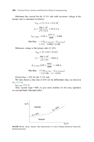
Choose bias 5 22% for the 11 kV side.
We then choose a bias slop of 22% for the differential relay (as shown in
Fig. 19.5.6):
I diff. min 5 0.1 A
Note: second slope 5 80%, to give more stability for the relay operation
on external faults (through faults).
FIGURE 19.5.6 Relay operate bias characteristic of a three-winding transformer biased dif-
ferential protection.