
Page 302 - Practical Power System and Protective Relays Commissioning
P. 302
296 Practical Power System and Protective Relays Commissioning
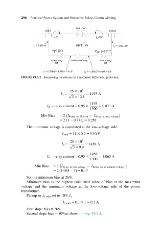
FIGURE 19.5.2 Interposing transformer in transformer differential protection.
25 3 10 3
I 2 5 p ffiffiffi 5 1193 A
3 3 12:1
1193
I R 5 relay current 5 0:95 3 5 0:871 A
1300
Min Bias 5 2 I Relay set Normal I Relay at max voltage
5 21 0:871Þ 5 0:256
ð
The minimum voltage is calculated at the low-voltage side.
V min 5 11 3 0:9 5 9:9kV
25 3 10 3
I 2 5 p ffiffiffi 5 1458 A
3 3 9:9
1458
I R 5 relay current 5 0:95 3 5 1:065 A
1300
Min Bias 5 2 I Relay at min voltage I Relay set at nominal voltage
5 21:065 2 1Þ 5 0:13
ð
Set the minimum bias at 26%.
Minimum bias is the highest calculated value of bias at the maximum
voltage and the minimum voltage at the low-voltage side of the power
transformer.
Pickup or I d min set to 10% I n
I d min 5 0:1 3 1 5 0:1A
First slope bias 5 26%
Second slope bias 5 80%as shown in Fig. 19.5.3.