Page 305 - Practical Power System and Protective Relays Commissioning
P. 305

Protection Relays Settings Chapter | 19  299


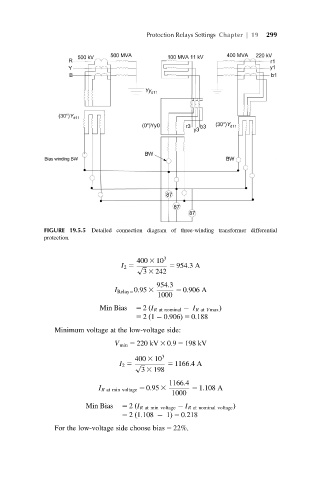
             FIGURE 19.5.5 Detailed connection diagram of three-winding transformer differential
             protection.


                                      400 3 10 3
                                  I 2 5 p ffiffiffi  5 954:3A
                                        3 3 242
                                           954:3
                                I Relay5 0:95 3  5 0:906 A
                                            1000
                            Min Bias  5 2 I R at nominal   I R at Vmax Þ
                                         ð
                                      5 21   0:906Þ 5 0:188
                                         ð
                Minimum voltage at the low-voltage side:
                                V min 5 220 kV 3 0:9 5 198 kV
                                     400 3 10 3
                                 I 2 5 p ffiffiffi  5 1166:4A
                                       3 3 198
                                               1166:4
                            I R at min voltage 5 0:95 3  5 1:108 A
                                               1000
                        Min Bias  5 2 ðI R at min voltage   I R at nominal voltage Þ
                                  5 21:108   1Þ 5 0:218
                                     ð
                For the low-voltage side choose bias 5 22%.
   300   301   302   303   304   305   306   307   308   309   310