
Page 308 - Practical Power System and Protective Relays Commissioning
P. 308
302 Practical Power System and Protective Relays Commissioning
500
I through fault 220kV side 5 9237:6 5 20994:5A
220
I through fault 500 kV side
V S1 5 :R Loop1
CT HV side
9237:6
5 5 5:5 5 84:678 V
600
I through fault 220 kV side 20; 994:5
V S2 5 5 8 5 167:956 V
CT LV side 1000
V S2 . V S1
Then choose V S 5 V S2 .
Use the relay with set voltage 25 175 V with 25-V taps. Choose
V S 5 170 V:
R V burden 5 1VA
Also choose CT knee point at least 2V S
VK min 5 2 3 170 V
5 340 V
Choose VK 5 400 V for CT, when another relay (current relay) R 1 is
used with the voltage relay in parallel and given that the burden of current
relay is 600 Ω and its current is 40 mA.
Then the voltage of the current relay (R 1 ) is 600 3 0.040 5 24 V.
Then the series setting resistor of the current relay R 1 can be calculated
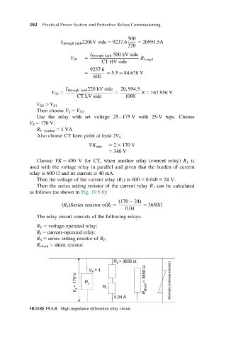
as follows (as shown in Fig. 19.5.8):
ð170 2 24Þ
ðR S ÞSeries resistor ofR I 5 5 3650Ω
0:04
The relay circuit consists of the following relays:
R V 5 voltage-operated relay;
R I 5 current-operated relay;
R S 5 series setting resistor of R I ;
R shunt 5 shunt resistor.
FIGURE 19.5.8 High-impedance differential relay circuit.