
Page 309 - Practical Power System and Protective Relays Commissioning
P. 309
Protection Relays Settings Chapter | 19 303
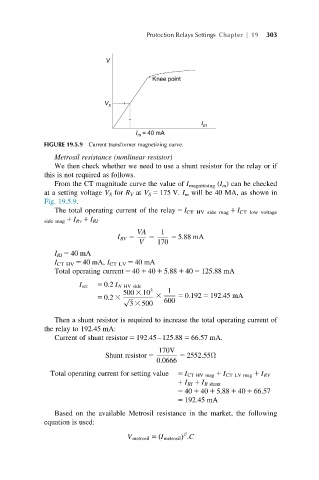
FIGURE 19.5.9 Current transformer magnetizing curve.
Metrosil resistance (nonlinear resistor)
We then check whether we need to use a shunt resistor for the relay or if
this is not required as follows.
From the CT magnitude curve the value of I magnitising (I m ) can be checked
at a setting voltage V S for R V at V S 5 175 V. I m will be 40 MA, as shown in
Fig. 19.5.9.
The total operating current of the relay 5 I CT HV side mag 1 I CT low voltage
side mag 1 I Rv 1 I RI
VA 1
I RV 5 5 5 5:88 mA
V 170
I RI 5 40 mA
I CT HV 5 40 mA, I CT LV 5 40 mA
Total operating current 5 40 1 40 1 5.88 1 40 5 125.88 mA
I set 5 0:2 I N HV side
500 3 10 3 3 1
5 0:2 3 p ffiffiffi 600 5 0:192 5 192:45 mA
3 3 500
Then a shunt resistor is required to increase the total operating current of
the relay to 192.45 mA:
Current of shunt resistor 5 192.45 125.88 5 66.57 mA.
170V
Shunt resistor 5 5 2552:55Ω
0:0666
Total operating current for setting value 5 I CT HV mag 1 I CT LV mag 1 I RV
1 I RI 1 I R shunt
5 40 1 40 1 5:88 1 40 1 66:57
5 192:45 mA
Based on the available Metrosil resistance in the market, the following
equation is used:
β
V metrosil 5 ðI metrosil Þ :C