
Page 303 - Practical Power System and Protective Relays Commissioning
P. 303
Protection Relays Settings Chapter | 19 297
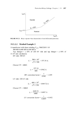
FIGURE 19.5.3 Relay operate bias characteristic of used differential protection.
19.5.2.2 Worked Example 2
A transformer with three-winding Y yd11 500/220/11 kV
500 MVA/400 MVA/100 MVA
Tap changer 56 10% of 220 kV side and tap charger 56 10% of
11 kV side calculation.
HV side: 500 kV
500 3 10 3
I 1 5 p ffiffiffi 5 577:35 A
3 3 500
Choose CT 5 600/1
577:35
i 1 5 5 0:962 A
600
1
HV correction factor 5 5 1:039
0:962
LV side: 220 kV side
400 3 10 3
I 2 5 p ffiffiffi 5 1049:72 A
3 3 220
Choose CT 5 1000/1
1049:72
i 2 5 5 1:0497 A
1000
1
LV correction factor 5 5 0:952
1:0497