
Page 297 - Practical Power System and Protective Relays Commissioning
P. 297
Protection Relays Settings Chapter | 19 291
1. Z st # 0.5 Z L min ; this means less than half of the minimum load
impedance;
2. Z st $ 1.25 Z 3 .
t st 5 1.3 second.
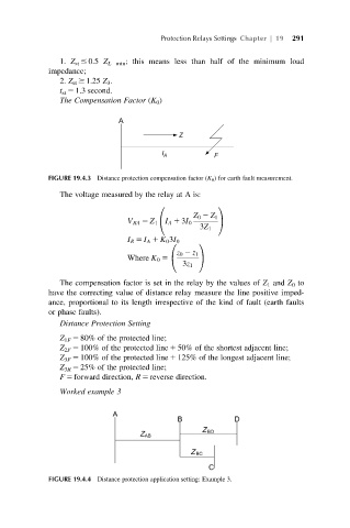
The Compensation Factor (K 0 )
FIGURE 19.4.3 Distance protection compensation factor (K 0 ) for earth fault measurement.
The voltage measured by the relay at A is:
0 1
Z 0 2 Z 1
V RA 5 Z 1 I A 1 3I 0 A
@
3Z 1
I R 5 I A 1 K 0 3I 0
0 1
z 0 2 z 1
Where K 0 5 @ A
3z 1
The compensation factor is set in the relay by the values of Z 1 and Z 0 to
have the correcting value of distance relay measure the line positive imped-
ance, proportional to its length irrespective of the kind of fault (earth faults
or phase faults).
Distance Protection Setting
Z 1F 5 80% of the protected line;
Z 2F 5 100% of the protected line 1 50% of the shortest adjacent line;
Z 3F 5 100% of the protected line 1 125% of the longest adjacent line;
Z 3R 5 25% of the protected line;
F 5 forward direction, R 5 reverse direction.
Worked example 3
FIGURE 19.4.4 Distance protection application setting: Example 3.