
Page 324 - Practical Power System and Protective Relays Commissioning
P. 324
318 Practical Power System and Protective Relays Commissioning
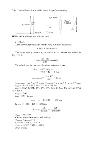
FIGURE 19.7.4 Check the zone (CH) relay circuit.
I 5 30 mA
Then, the voltage across the current relay R I will be as follows:
5 3500 3 0:03 5 105V
The series setting resistor R S is calculated as follows (as shown in
Fig. 19.7.4):
125 2 105
R S 5 5 666 Ω
0:03
Then check whether we need the shunt resistance or not:
I set 5 0:15 I fault min
5 0:15 3 12 5 1:8KA
1:8 3 10 3
I set secondary 5 5 1:5A
1200
I total operation 5 I RV 1 I RI 1 I CT2 mag 1 I CT4 mag 1 I CT8 mag 1 I CT10 mag 1 I R shunt
I total 5 35 1 30 1 35 1 35 1 35 1 35 5 205 mA
I mag 5 40 mA for CT 2 ,CT 4 ,CT 8 ,CT 10 from V I mag . The curve of CT at
V S 5 125 V
I mag 5 35 mA
I total 5 205 1 I R shunt
3
I total 5 I set 5 1:5 3 10 5 1500 mA
I R shunt 5 1500 205 5 1295 mA
VS 125
R shunt 5 5
IRshunt 1295=1000
R shunt 5 96.525 Ω
Choose metrosil resistance with voltage:
β
V metrosil 5 (I metrosil ) C
C 5 450, β 5 0.25, I 5 30 A
V metrosil 5 (30) 0.25 450 5 1053 V
Relay setting