
Page 320 - Practical Power System and Protective Relays Commissioning
P. 320
314 Practical Power System and Protective Relays Commissioning
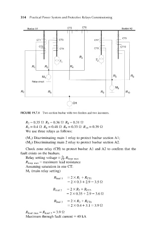
FIGURE 19.7.1 Two-section busbar with two feeders and two incomers.
R 2 5 0.35 Ω R 5 5 0.36 Ω R 8 5 0.31 Ω
R 3 5 0.4 Ω R 6 5 0.48 Ω R 9 5 0.33 Ω R 10 5 0.39 Ω
We use three relays as follows:
(M 1 ) Discriminating main 1 relay to protect busbar section A1;
(M 2 ) Discriminating main 2 relay to protect busbar section A2.
Check zone relay (CH) to protect busbar A1 and A2 to confirm that the
fault exists on the busbars.
Relay setting voltage 5 I F
CT R loop max
R loop max 5 maximum lead resistance
Assuming saturation in one CT:
M 1 (main relay setting)
R lead 1 5 2 3 R 1 1 R CT1
5 2 3 0:3 1 2:9 5 3:5 Ω
R lead 2 5 2 3 R 2 1 R CT3
5 2 3 0:35 1 2:9 5 3:6 Ω
R lead 3 5 2 3 R 3 1 R CT6
5 2 3 0:4 1 3:1 5 3:9 Ω
R lead max 5 R lead 3 5 3.9 Ω
Maximum through fault current 5 40 kA