
Page 325 - Practical Power System and Protective Relays Commissioning
P. 325
Protection Relays Settings Chapter | 19 319
Main 1 zone (discriminating zone)—M 1
R V V range 25 175 V, I RV 5 35 mA, V set 5 130 V
R I burden 5 3500 Ω, I RV 5 30 mA, R S 5 833 Ω
R shunt 5 99.23 Ω, Metrosil C 5 450 β 5 0.25 I 5 30 A at 2 seconds.
Main 2 zone (discriminating zone)—M 2
R V V range 5 25 175 V, I RV 5 35 mA, V set 5 130 V
R I burden 5 3500 Ω, I RV 5 30 mA, R S 5 833 Ω
R shunt 5 99.23 Ω, Metrosil C 5 450, β 5 0.25, I 5 30 A at 2 seconds.
Check zone (CH)
R V V range 5 25 175 V, I RV 5 35 mA, V set 5 125 V
R I burden 5 3500 Ω, I RV 5 30 mA, R S 5 666 Ω
R shunt 5 96.525 Ω, Metrosil C 5 450, β 5 0.25, I 5 30 A at 2 seconds.
19.7.3 INTRODUCTION TO BREAKER FAILURE PROTECTION
This protection is used as backup protection to isolate a fault if the circuit
breaker of the feeder has a mechanical or other problem preventing it from
opening the circuit. This protection then isolates all sources which feed the
fault and also the remote end of the line.
19.7.4 WORKED EXAMPLE FOR BREAKER FAILURE
PROTECTION
CB failure time
t CB 5 110 180 ms
Fault clearance time should not exceed 300 ms
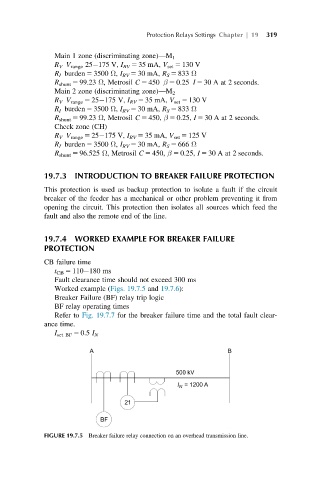
Worked example (Figs. 19.7.5 and 19.7.6):
Breaker Failure (BF) relay trip logic
BF relay operating times
Refer to Fig. 19.7.7 for the breaker failure time and the total fault clear-
ance time.
I set BF 5 0.5 I N
FIGURE 19.7.5 Breaker failure relay connection on an overhead transmission line.