
Page 322 - Practical Power System and Protective Relays Commissioning
P. 322
316 Practical Power System and Protective Relays Commissioning
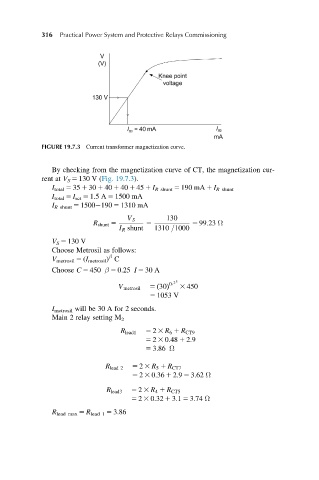
FIGURE 19.7.3 Current transformer magnetization curve.
By checking from the magnetization curve of CT, the magnetization cur-
rent at V S 5 130 V (Fig. 19.7.3).
I total 5 35 1 30 1 40 1 40 1 45 1 I R shunt 5 190 mA 1 I R shunt
I total 5 I set 5 1.5 A 5 1500 mA
I R shunt 5 1500 190 5 1310 mA
V S 130
R shunt 5 5 5 99:23 Ω
I R shunt 1310 =1000
V S 5 130 V
Choose Metrosil as follows:
β
V metrosil 5 (I metrosil ) C
Choose C 5 450 β 5 0.25 I 5 30 A
2 5
00
V metrosil 5 30ðÞ 3 450
5 1053 V
I metrosil will be 30 A for 2 seconds.
Main 2 relay setting M 2
R lead1 5 2 3 R 6 1 R CT9
5 2 3 0:48 1 2:9
5 3:86 Ω
R lead 2 5 2 3 R 5 1 R CT7
5 2 3 0:36 1 2:9 5 3:62 Ω
R lead3 5 2 3 R 4 1 R CT5
5 2 3 0:32 1 3:1 5 3:74 Ω
R lead max 5 R lead 1 5 3.86