
Page 321 - Practical Power System and Protective Relays Commissioning
P. 321
Protection Relays Settings Chapter | 19 315
I F
V S 5 : R loop max
CT
40; 000
5 3:9 5 130 V
1200
Choose voltage relay R V as follows:
Range 25 175 V I RV 5 35 mA
Set V S 5 130 V
Then the knee point voltage of CT should be as follows:
V K min 5 2 3 V S
5 2 3 130 5 260 V
Choose V K 5 300 V
Use a current relay with burden 5 3500 Ω
I 5 30 mA
Then the voltage across the current relay R I is as follows:
3500 3 0.03 5 105 V.
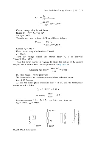
Then, the series resistor is required to adjust the setting of the current
relay R I and is calculated as follows (as shown in Fig. 19.7.2):
130 2 105
R S Setting Resistorð Þ 5 5 833 Ω
0:03
M 1 relay circuit—busbar protection
We then need to check whether we need shunt resistance or not:
I set 5 0.15 I fault min
Assume the single-phase minimum fault 5 12 kA, and the three-phase
minimum fault 5 14kA:
I set 5 0:15 3 12 5 1:8kA
1800
I set secondary 5 5 1:5A
1200
I total operating current 5 I RV 1 I RI 1 I CT1 mag 1 I CT3 mag 1 I CT6 mag
I RV 5 35 mA I RI 5 30 mA
FIGURE 19.7.2 Relay circuit.