
Page 326 - Practical Power System and Protective Relays Commissioning
P. 326
320 Practical Power System and Protective Relays Commissioning
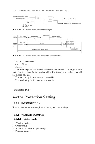
FIGURE 19.7.6 Breaker failure relay operation logic.
FIGURE 19.7.7 Breaker failure time and total fault clearance time.
5 0.5 3 1200 5 600 A
t CB 5 120 ms
Action:
The back trip for all feeders connected on busbar A through busbar
protection trip relays for the section which this feeder connected to it should
not exceed 300 ms.
The remote trip for the breaker is at end B.
The local retrip for the breaker is at end A.
Subchapter 19.8
Motor Protection Setting
19.8.1 INTRODUCTION
Here we provide some examples for motor protection settings.
19.8.2 WORKED EXAMPLES
19.8.2.1 Motor Faults
1. Winding faults
2. Overloading;
3. Reduced or loss of supply voltage;
4. Phase reversal;