
Page 161 - Principles of Catalyst Development
P. 161
CATALYST CHARACTERIZATION 149
TO NITROGEN ELECTRONIC
TO HELIUM MANOMETER
TO VACUUM PUMPS
VACUUM
VALVE
CALIBRATED
VOLUME
VACUUM
COUPLING
FLASK
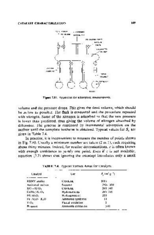
Figure 7.11. Apparatus for adsorption measurements.
volume and the pressure drops. This gives the dead volume, which should
be as low as possible. The flask is evacuated and the procedure repeated
with nitrogen. Some of the nitrogen is adsorbed so that the new pressure
is lower than predicted, thus giving the volume of nitrogen absorbed by
difference. The process is continued by incremental adsorption on the
surface until the complete isotherm is obtained. Typical values for Sg are
given in Table 7.4.
In practice, it is inconvenient to measure the number of points shown
in Fig. 7.10. Usually a minimum number are taken (2 or 3), each requiring
about thirty minutes. Indeed, for routine determinations, c is often known
with enough confidence to justify one point. Even if c is not available,
equation (7.7) shows that ignoring the intercept introduces only a small
TABLE 7.4. Typical Surface Areas for Catalysts
Catalyst Use Sg(m'g~l)
REHY zeolite Cracking 1000
Activated carbon Support 500- :1000
SiOrAl,OJ Cracking 200-S00
CoMo/Al,O, Hydrotreating 200-300
Nij Al,O, Hydrogenation 250
Fe-A1,Or K,O Ammonia synthesis 10
V,Os Partial oxidation 1
Pt gauze Ammonia oxidation 0.01