
Page 287 - Process Modelling and Simulation With Finite Element Methods
P. 287
274 Process Modelling and Simulation with Finite Element Methods
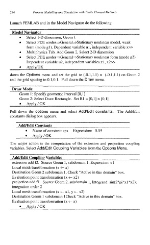
Launch FEMLAB and in the Model Navigator do the following:
Model Navigator
Select 1-D dimension, Geom 1
Select PDE modes*General==Stationary nonlinear model, weak
form (mode gl). Dependent variable ul, independent variable x>>
0 Multiphysics Tab. Add Geom 2, Select 2-D dimension
Select PDE modes+General=Stationary nonlinear form (mode 82)
Dependent variable u2, independent variables xl, x2>>
down the Options menu and set the grid to (-0.1,l.l) x (-0.1,l.l) Geom 2
on
and the grid spacing to 0.1,O.l. Pull down the Draw menu.
Draw Mode
Geom 1: Specify geometry; interval [0,1]
Geom 2: Select Draw Rectangle. Set R1 = [0,1] x [0,1]
ApplylOK
Pull down the options menu and select Add/Edit constants. The AddEdit
constants dialog box appears.
Add/Edit Constants
Name of constant: eps Expression: 0.05
Apply/OK
The major action is the computation of the extrusion and projection coupling
variables. Select Add/Edit Coupling Variables from the Options Menu.
AddEdit Coupling Variables
extrusion add f2. Source Geom 1, subdomain 1, Expression: ul
Local mesh transformation (x t x)
Destination Geom 2 subdomain 1, Check “Active in this domain” box.
Evaluation point transformation (x t x2)
projection add fl. Source Geom 2, subdomain 1, Integrand: sin(2*pi*xl *x2);
integration order 2
Local mesh transformation (x t xl, y t x2)
Destination Geom 1 subdomain lCheck “Active in this domain” box.
Evaluation point transformation (x t x)
Apply/OK